
Home › Forum › Ask A Member › Testing timing of Red Atom Modules › Re: Testing timing of Red Atom Modules

It’d be nice to have a digital ‘scope with freeze frame. Mine’s an old Gould OS250B dual-trace analogue that I picked up when the technical college auctioned them all off in the nineties. I got it for a fiver ’cause the casing was held together with tape. Enough of that, this is the AOMCI not pimp-my-scope.
Well, I got the replacement TIP162s and tested them and they’re all good, so I rigged a module with a leaf spring terminal block so I could test them with the engine by switching back to contacts and then change transistors and then switch over to the module.
There is a certain amount of variation between them that affects timing, in one case quite a lot. We would have expected that the hfe would not really have much of an effect because this circuit is basically a cascade switch with positive feedback, but it might be the inefficiency when turning on that’s the issue.
It’s led me to realise that I need to make some allowance for variation or select transistors specifically for the most consistent performance.
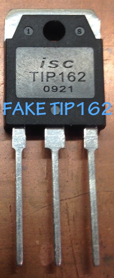
For those who choose to go down the same path as me, I’ve attached a pic of the dodgy TIP162. Next step is to try some BU941ZPFI transistors, they’e cheaper and more readily available.
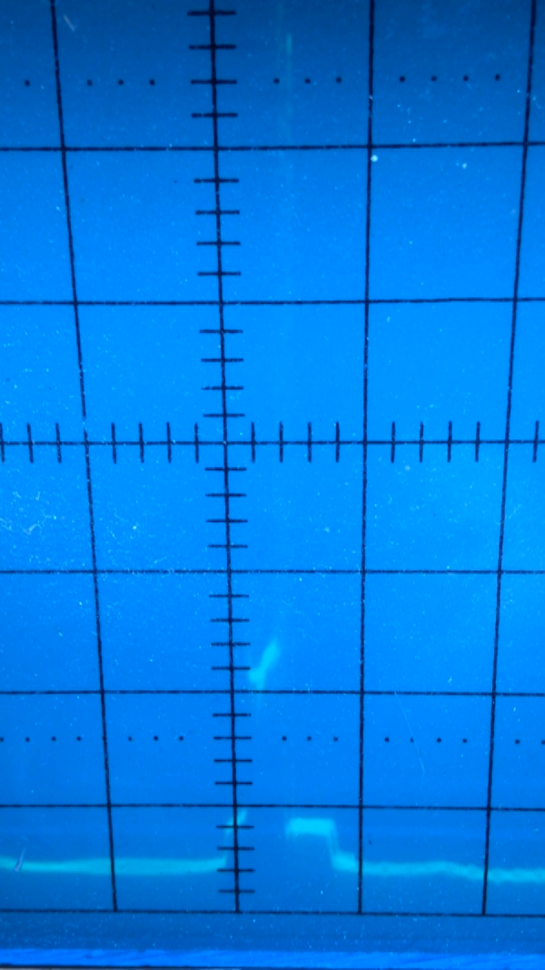
Scope trace:
I’ve attached a shot from that earlier run where I couldn’t get a proper trigger so there are two cycles overlaid. What’s visible in some of shots from that run is a spike of 30 to 50 volts toward the tail end of the switch off. The vertical axis is 5V/div.
I was working toward getting some better traces by improving the trigger using a coil in the proximity of the ignition lead to pick up a trigger pulse. I was managing the timebase and engine speed to try and get two sparks across the trace, and then expand it to enlarge the area of interest. I was nearly there when I ran out of fuel. It was time for dinner anyway.
Attachments: