

Home › Forum › Ask A Member › Testing timing of Red Atom Modules › Re: Testing timing of Red Atom Modules

About the timing change in the ATOM modules at different RPMs…….this is completely expected. I’ll try to explain.
In a conventional (magneto / breaker points) ignition system, the spark is timed with mechanical points being moved
by the lobe on a cam. The "break point" is the exact same location, no matter what the RPM (assuming you are
NOT rotating the distributor plate). The points open up when current through the primary of the spark coil is at
maximum. The position of the magnets in the flywheel, and the "pickup coil" and the position of the points are
all mechanically arranged for the points to open when coil current is at maximum. This changes very little with
RPM.
In contrast, the ATOM module is triggered by VOLTAGE ACROSS THE POWER DARLINGTON. This voltage across the
power darlington is roughly proportional to the current going through it……..but, the ATOM module doesn’t "know"
when the current is at maximum……….so, they GUESS, by setting the "trip point" slightly early at lower RPM. (maybe
2 or 3 degrees early at 500 RPM.) The resistor pair R2 and R3 form a voltage divider, that sets this initial voltage
"trip point".
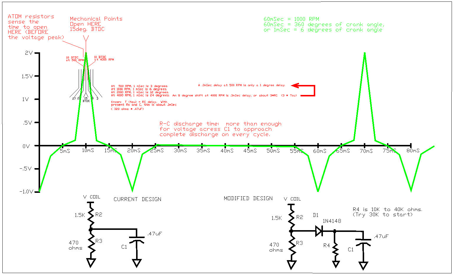
Capacitor C1, in combination with the resistance of R2 and R3 in parallel, forms a low-pass simple R-C filter.
(Time delay T, or "tau", is simply R*C). As the parallel combination of R2 and R3 is about 320 ohms, against a .47uF capacitor,
this will give you a "tau" delay of about .1 millisecond…..or about a 2 degree timing DELAY at 500 RPM.
Please note that this time delay is a FIXED VALUE in TIME. (This is about 3 * TAU delay, or .3 mSec).
SO……the R2/R3 split was probably setting the "trip point" at about 20 degrees before top dead center.
The R2/R3 * C1 "filter delay" sets that back about 2 degrees, so you see the actual "firing point" at about 18
degrees Before Top Dead Center (as compared to the 15 degrees you saw with points). This isn’t enough of
a timing error for most people to notice.
Now, at higher RPM (say, 4000 RPM)….things change dramatically. Specifically:
1) The voltage created by the higher RPM is about double or more what you see at lower RPM…..
so the voltage-based "trip point" sensed by R2/R3 is a bit earlier (maybe a degree or two.)
HOWEVER —
2) The RC timing delay is FIXED………and what caused only a 1 or 2 degree timing delay at 500 RPM,
has 8 times that effect at 4000 RPM. ….8 to 10 degrees of additional delay.
So, yes, while the voltage trip point is SENSED a few degrees earlier at higher RPM, the fixed timing
delay of about .3 milliseconds causes the final "firing point" to be about 8 degrees LATER than you see
at only 500 RPM.
This explains why (with the ATOM) you see 18 degrees BTDC at 500 RPM, and only 10 degrees BTDC at 4000 RPM.
You get an additional 8 degrees of delay at the higher RPM…..due entirely to the R-C timing delay of the
R-C "filter" formed by R2, R3 and C1. (This delay also has a filter function, to prevent false triggering
and erratic timing, so you really can’t eliminate C1.)
SO………compared to the "points" that give you a fixed 15 degrees BTDC firing point at any RPM, the ATOM
fires about 3 degrees too early at idle, and about 5 degrees too late at higher RPM. MOST USERS of
chain saws, lawn mowers (etc) would never notice this. And, frankly, most outboard motor people that
used the ATOM didn’t have oscilloscopes, so they never really noticed the timing discrepancies either.
The ATOM was "good enough" for most people………..except people who really want good performance.
See the attached timing diagram (attached to this e-mail message)
See: Atom_RC_Delay.jpg
Now, this R-C filter timing delay is fixed, (in the current design). You CAN compensate for this by having
the capacitor hold a bit of voltage with increasing RPM, and you can probably get several degrees of timing
adjustment closer to the 15 degrees desired by doing this.
Look at the schematics at the bottom of my drawing. The schematic to the left is the "stock" ATOM
design. Resistors R2 and R3, along with C1, form a RC low pass filter (and fixed timing delay). By
putting a diode in series with the line going to C1, and a SEPARATE "discharge resistor" (R4), you can
have C1 pump up a voltage proportional to the RPM, which will adjust the timing earlier. R4 controls
the rate of discharge (and hence, the voltage adjustment). R4 should be somewhere between 10K and
40K ohms……..( I don’t have the time to work out the details here.)
Also, the .7V drop across the small signal diode will screw with the initial "trip point", so R2 will probably
have to be adjusted lower to compensate for that diode drop.
*********** Anyhow, the ATOM was "good enough" for most people. If you really want to design a replacement
that will work extremely well across all RPM, and across many different types of spark coils, ….that’s going to
take some serious effort.
–Bill Mohat AOMCI, Cleveland, Western Reserve Chapter
Attachments:
***********************************************************************
Bill Mohat MS/CIS, BSEET, CCNA
"You can avoid reality, but you cannot avoid the consequences of avoiding reality." --Ayn Rand **********************************************