

Home › Forum › Ask A Member › Testing Solenoids › Re: Testing Solenoids

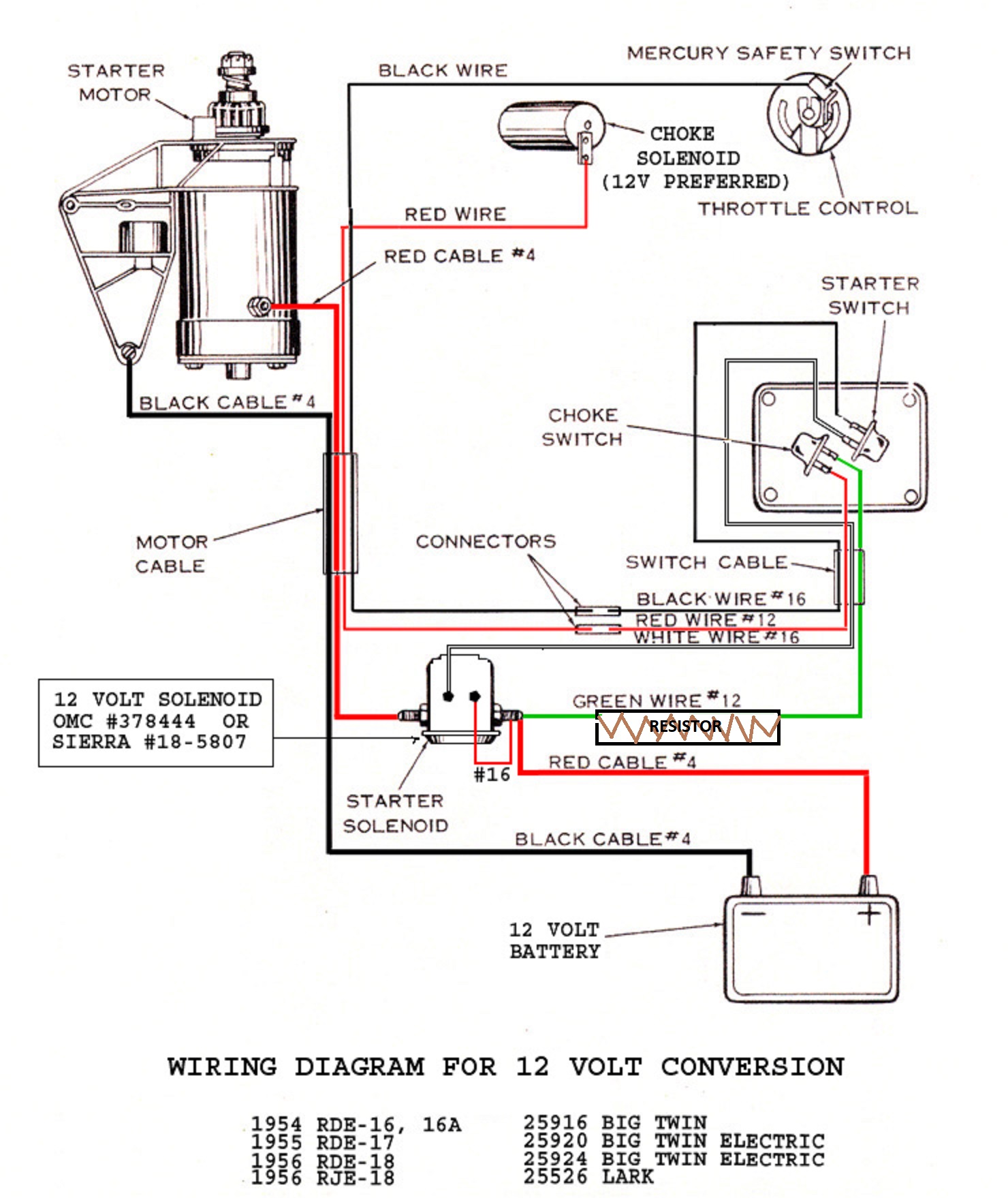
Frank, thanks for the clarification. The way the conversion diagram was, it didn’t make much sense.
I do plan in keeping the 6v choke solenoid, at least for now, as it works fine.
I presume, with the edited diagram, this is the way to way the resistor?
The resistor I bought, is as described below.
Sound okay to you?
——————————————-
"Aftermarket Replacement Electrical Ignition Resistor (0.6 OHM Resistor) made to fit Ford Tractor models:
2N, 8N, 9N with 12 volt conversion (1939-1950).
Used in alternator conversion kits.
Replace Part Number: 8NE10306"
—————————————–
I’m still wondering, is it the wrong 6v or wrong 12v solenoid that will fry the mercury switch,
and what’s the internal differences, and how do you tell the difference using a VOM?
Thanks again!
Attachments:
Prepare to be boarded!