

Home › Forum › Ask A Member › Testing timing of Red Atom Modules › Re: Testing timing of Red Atom Modules

I’m new to this discussion thread, but I think I can be of some help.
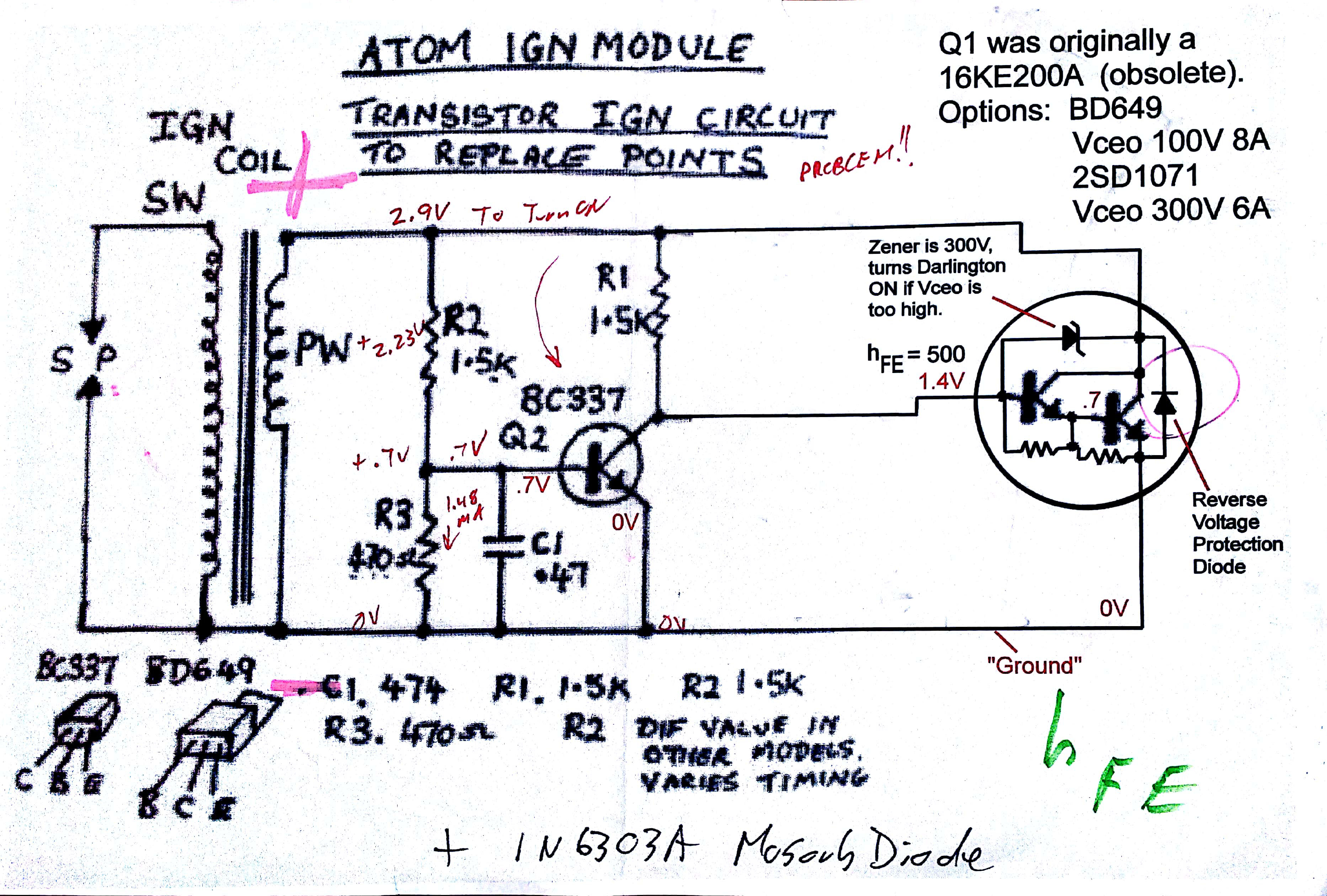
Please look at the attached file: AtomRedSchem_1.jpg Is this the schematic you are working from?
I think it is.
Please note that I changed the schematic symbol for the power darlington…..the original symbol was not
correct, and you can’t understand how this module operates if the schematic symbol is not correct. I think
the symbol I used was for a 2SD1071.
Anyhow…. all solid state "points replacement" modules (be they Atoms or anyone elses’) …they all face
the same dilemma. In your original magneto with the points closed, the voltage across the primary winding (PW)
is ZERO, as the points short that voltage out completely. If the "switch" in your solid state module did the same,
you would have NO VOLTAGE to work with, and you could not turn the "switch" off. Nasty little design problem there.
The "solution" to that dilemma is that power darlingtons are VERY INEFFICIENT; they waste a lot of voltage
across them, even when "on" to the maximum possible. When the primary coil is generating that big positive
voltage spike, the power darlington does not completely short it out (like your points would do). Instead, you
get a voltage drop across the power darlington, porportional to the current that’s going through the device.
According to the values in this schematic, when the voltage drop across the power darlington reaches about 2.9
volts, Q2 will turn on, and short out the Base of the power darlington, turning it OFF (i.e. "opening the points").
When using points, the cam opens your points when the positive voltage spike is at maximum voltage, or a little
later (because current lags voltage through an inductor, and you want to delay the points opening until you have
maximum current through the primary winding……which occurs slightly AFTER the voltage peak. But, in contrast,
the ATOM modules are "voltage drop" triggered, somewhere during the RISING SLOPE of the positive voltage spike….
about 2 to 5 degrees BEFORE your points will open up. (I’m just guessing here…..but it’s probably a good guess.
Has anyone ever measured this timing difference? Apparently someone has, because that seems to be the
content of this thread….trying to delay the spark timing generated by the ATOM module.)
If that is your goal, you have to realize the following:
1) The values of R2 / R3 set the "current trip" threshold of when the power darlington will turn OFF.
However, because of the steepness of the positive voltage spike, changing R2 or R3 will only alter
your timing by about one degree, at best.
Also, when your RPM goes up, the positive voltage spike will greatly increase in amplitude. When you
have points, this doesn’t change the timing. But, because the Atom design’s timing is based on a current level,
this will cause the Atom design to "trip" earlier at higher RPM, because the primary positive voltage spike
will have a higher peak value. This isn’t serious, probably the timing will advance by about 1 degree at
most, which is why nobody seems to have mentioned this before.
2) You can increase the value of C1….and that will delay the turn off of the Power Darlington a bit. But,
if you increase C1 by too much, you won’t turn off the power darlington at all (especially true at lower
RPM, when the positive voltage spike is at lower amplitude…..this might make the module stop working
completely at lower RPM, long before you see the delay you are looking for.) I expect increasing this
capacitor to .68uF (or thereabouts) will delay your spark a couple of degrees, but I don’t know what other
side effects it might give you.
3) At low RPM, your "positive voltage spike" might only be 5 or 6 volts, and the power darlington is wasting
about half of that voltage, decreasing the spark intensity at low RPM by about half. This might require
you to spin the motor faster to get it to start, compared to when you had points installed. This seems
to be a design problem for all of the currently existing "points replacement" designs I’ve looked at so far.
4) Any timing delay other than the simple "R-C" delay here (formed by R2/R3 and C1) ….any other type
of timing delay device will require a steady source of voltage (perhaps 3.3V or 5V)….which this design
currently does NOT have. To derive such a power source from the spiky voltages seen across the
primary windings would be a bit of a trick, to say the least.
**** Who is measuring these timing delays? Are you using an oscilloscope, or just a timing light on the
marks you are putting on the flywheel? What difference do you see between the points timing, and the
timing you are getting from these Atom modules? By exactly how much do you want to change the
timing of the Atom module?
***** Also, why are people looking at putting some kind of protection diode in this circuit? The 2SD1071
appears to be able to handle 300V, and has a reverse voltage protection diode built-in. (Or, are you using
something other than the 2SD1071?) If so, then what is your intended purpose for the protection diode?
What are you trying to protect against? What parts are failing when this diode is NOT present?
–Bill
Attachments:
***********************************************************************
Bill Mohat MS/CIS, BSEET, CCNA
"You can avoid reality, but you cannot avoid the consequences of avoiding reality." --Ayn Rand **********************************************