

Home › Forum › Ask A Member › Testing timing of Red Atom Modules › Re: Testing timing of Red Atom Modules

Debe,
Thanks for the help. I am going to get a lot of pics today.
I have had more luck with the BD 649s than the 1071s right now I am trying the TIP102s with good results since their readily available where I am getting parts.
I have noticed that OMC coils also have different manufactures and different positive and negative pulses produced so the polarity has to be reversed to module to get spark while motor is spinning in clockwise position. Is that caused because the windings in coil are opposite??
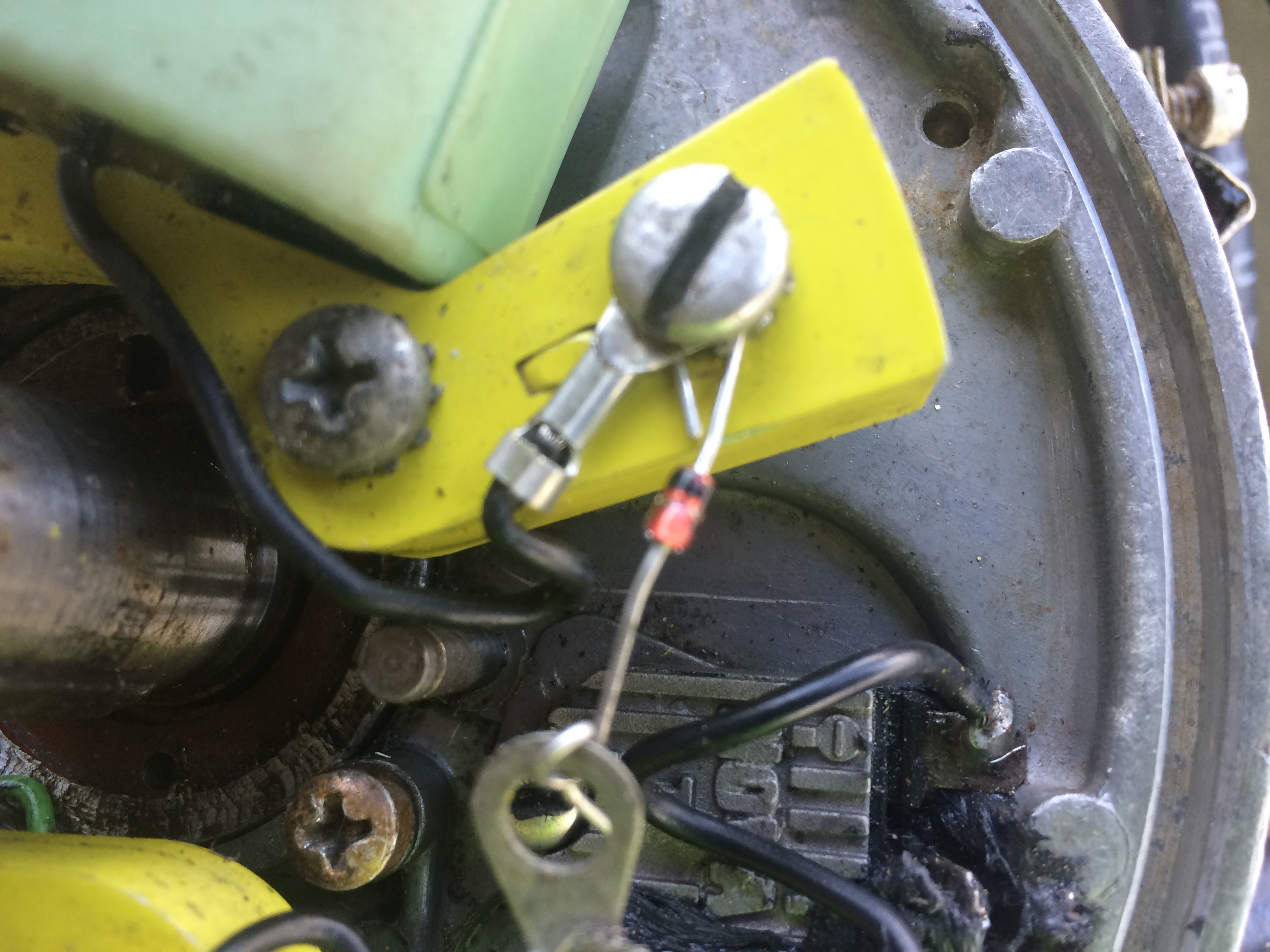
If motor does not spark clockwise I then spin it counter clockwise to see if spark is attained then I know to reverse the polarity to get spark while motor is spinning in clockwise direction. Some motors will have 2 different manufactured coils in them due to a past coil swap so it might be that each module has to be wired in reverse polarity for polarity to get spark while motor is spinning in clockwise position from both coils. I do this by just switching the small wires from coil the one that goes to ground I put it to the middle leg(leg C) of the larger transistor (BD649,2SD1071,currently trying a TIP102 with good results) and since I am screwing the larger transistor to the half a set of points the metal on the larger transistor has direct continuity with the middle leg of larger transistor (leg C). I then attach the smaller wire that would go to the points instead to ground. The wire I use from ground to the actual module leg E I do so using a one direction mosorb diode with the stripe on diode being grounded and the other side of diode going to leg E and that protects the circuit it also works on Nova2s and protects them while allowing them to work. Here is a pic of a diode being used to protect nova2 circuit its not a mosorb but it shows how I am doing it for them to protect them the black wire in photo is attached to diode goes to the negative side of nova2 and circuit fires as it should I have tried it with the mosorb and it works. Sorry for the crude pic but it shows how to do it.
here is where I get my 1 direction mosorb diodes just ordered 60
https://www.ebay.com/itm/20PCS-1-5-KE20 … 2749.l2649
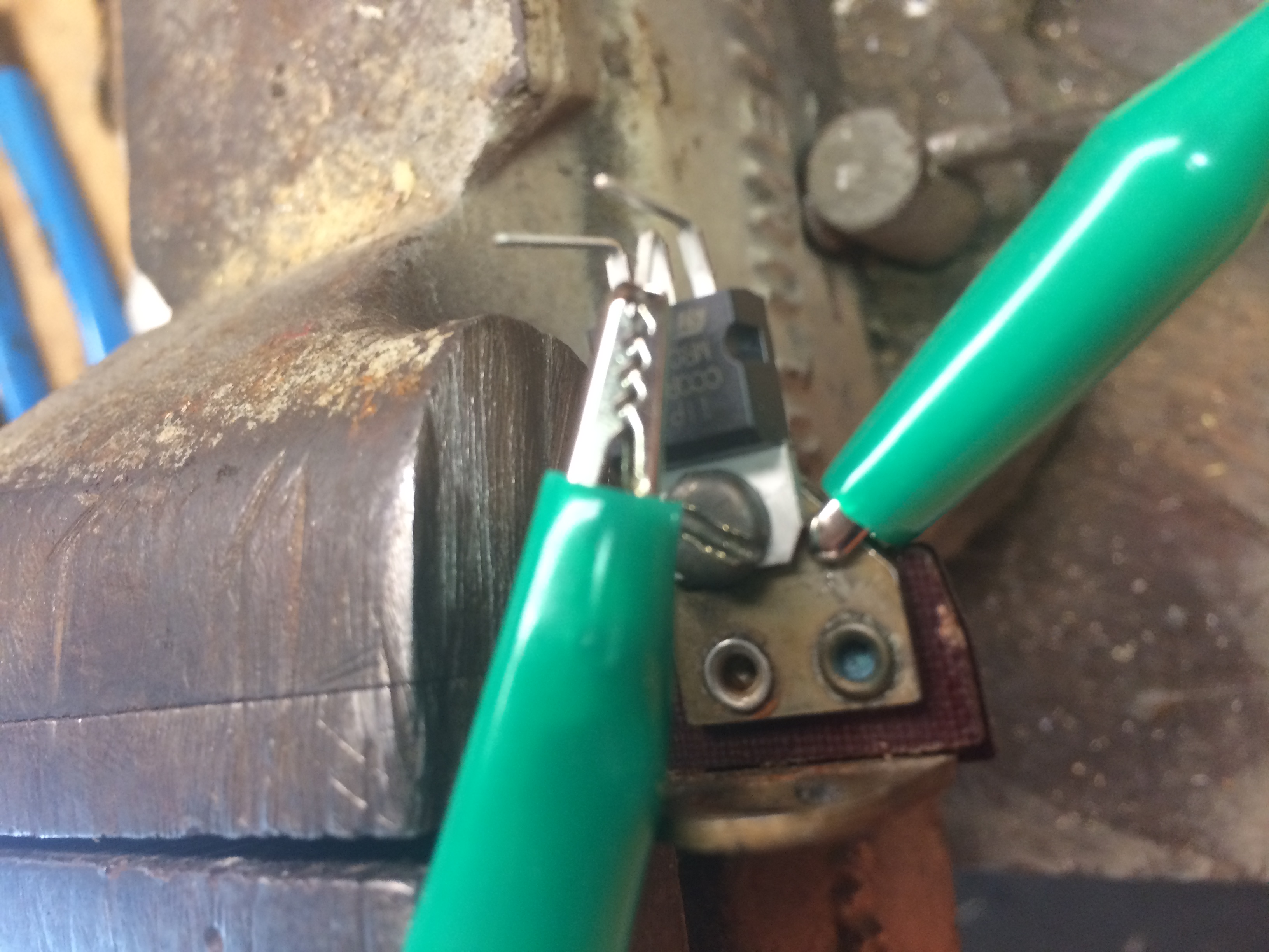
One question I have is it it ok to use the metal of larger transistor instead of the middle leg as a point to attach the positive pulse wire??
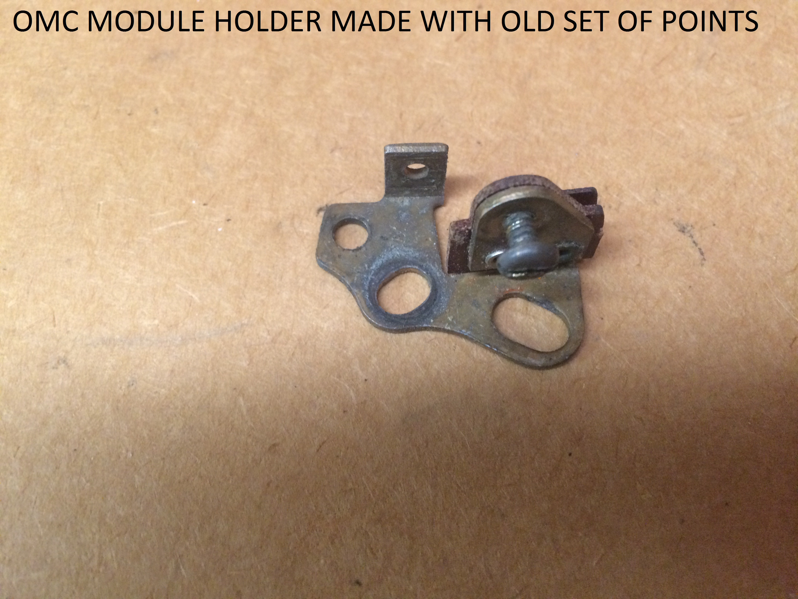
Here is what I attach module to notice the screw would go through the hole on larger transistor along with one of the smaller wires from coil.
continuity
This is how I attach small wire from coil to middle leg of large transistor you can also see the mosorb diode screwed to ground on one side and going to leg E or larger transistor.
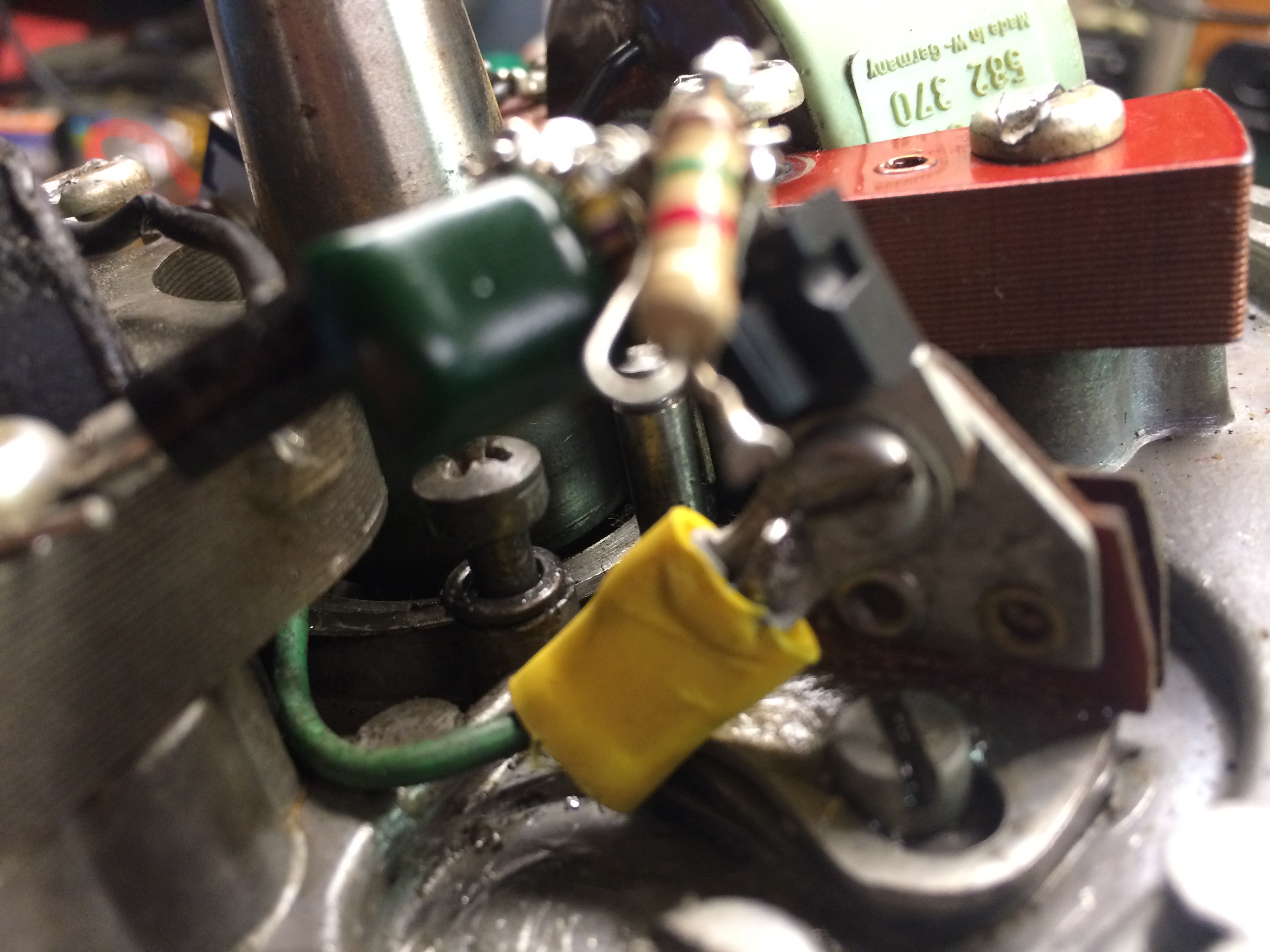
Again sorry for the crudness of my work and pics but it is experimental.
Joe
https://SecreLocal.com - - No Verify - Anonymous Adult Dating -