

Home › Forum › Ask A Member › 1957 15hp Evinrude › Re: 1957 15hp Evinrude

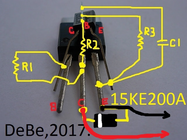
You guys have pretty much talked me into getting the tool. I do have his ring that goes around the coils to place them correctly and his 180 degree points adjuster tool for a 28hp up to ? and really like them. Bill I didn’t come up with the modules information Debe here did the whole thread can be read right here.
viewtopic.php?f=2&t=1050&hilit=modules
I am currently working on a list of parts I am using and a how to plus testing what I build that’s key also testing to make sure they hold up and engine performs well. These ones I have built for this 1956 seem to be working very well but I need to get the motor on a boat and make sure it winds up to high rpm’s and they don’t break down or fry and stop working so that’s next. I am also working on a finished product with a heat shield and insulation the rest the info below is how I am making them for testing purposes its quick and easy I can solder one together in 10 minutes max.
MODULES FOR TESTING PURPOSES BELOW:
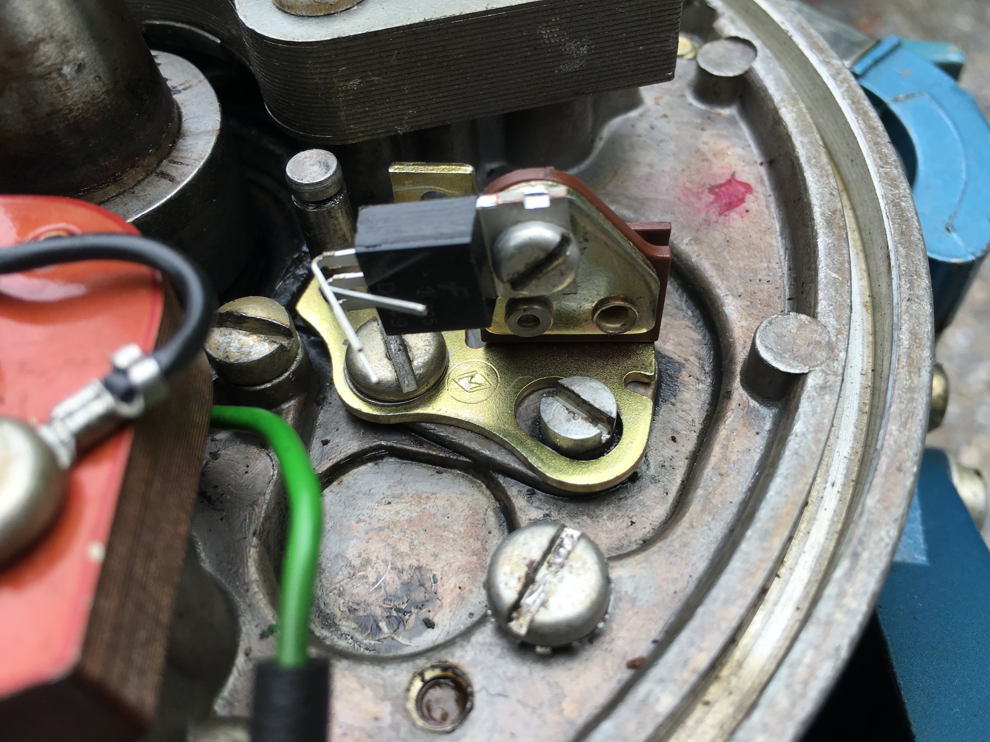
Here is how I am making them for Evinrude/Johnson 2 stroke 2 cylinder motors I use part of the old points to make them but I only screw my module to them and it could easily be unscrewed and the original entire set of points assembly put back. This is from page 22 of the thread above.
Keep in mind these are test modules not sealed with clear silicone or epoxy etc. They are a work in progress.
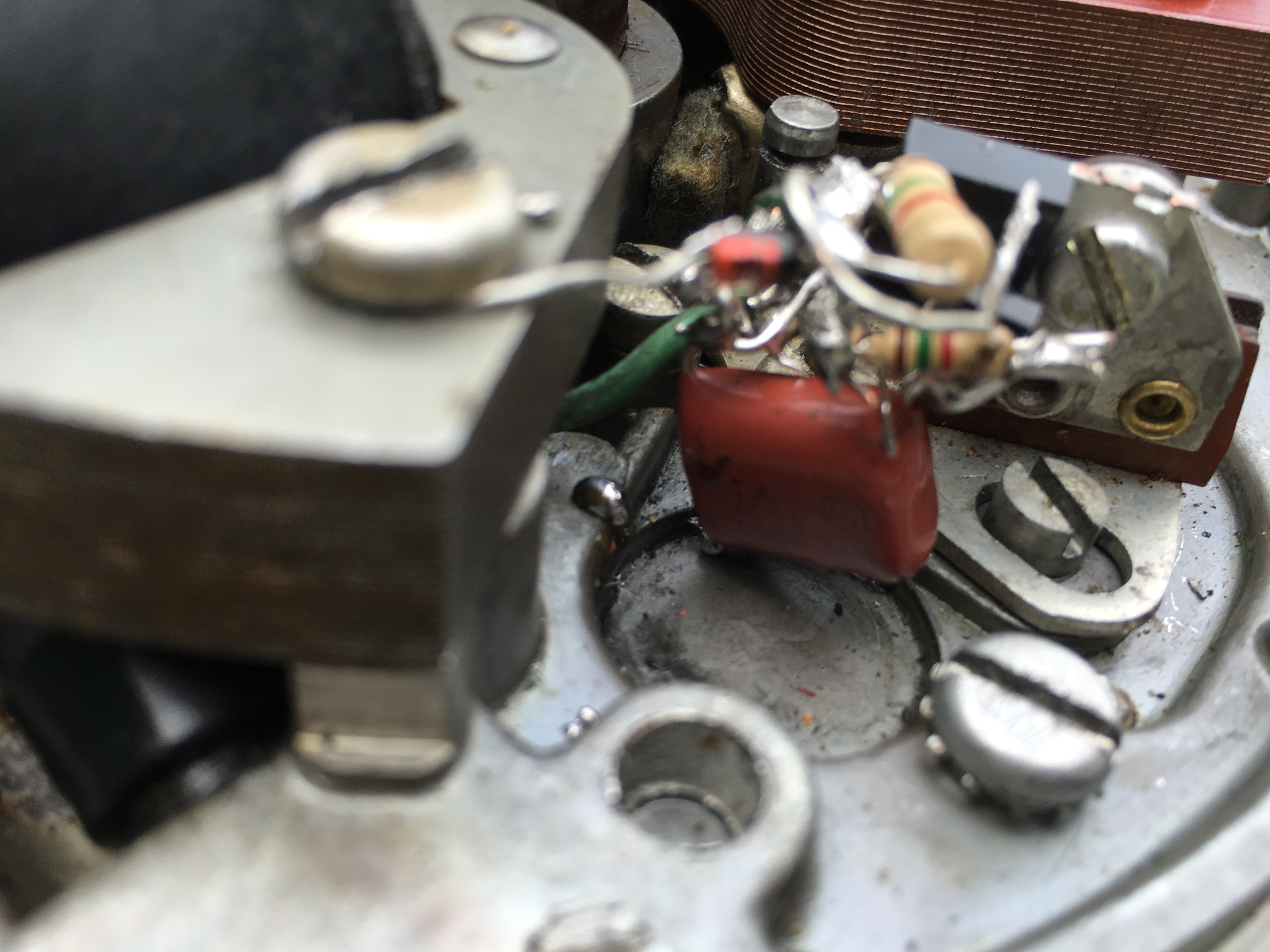
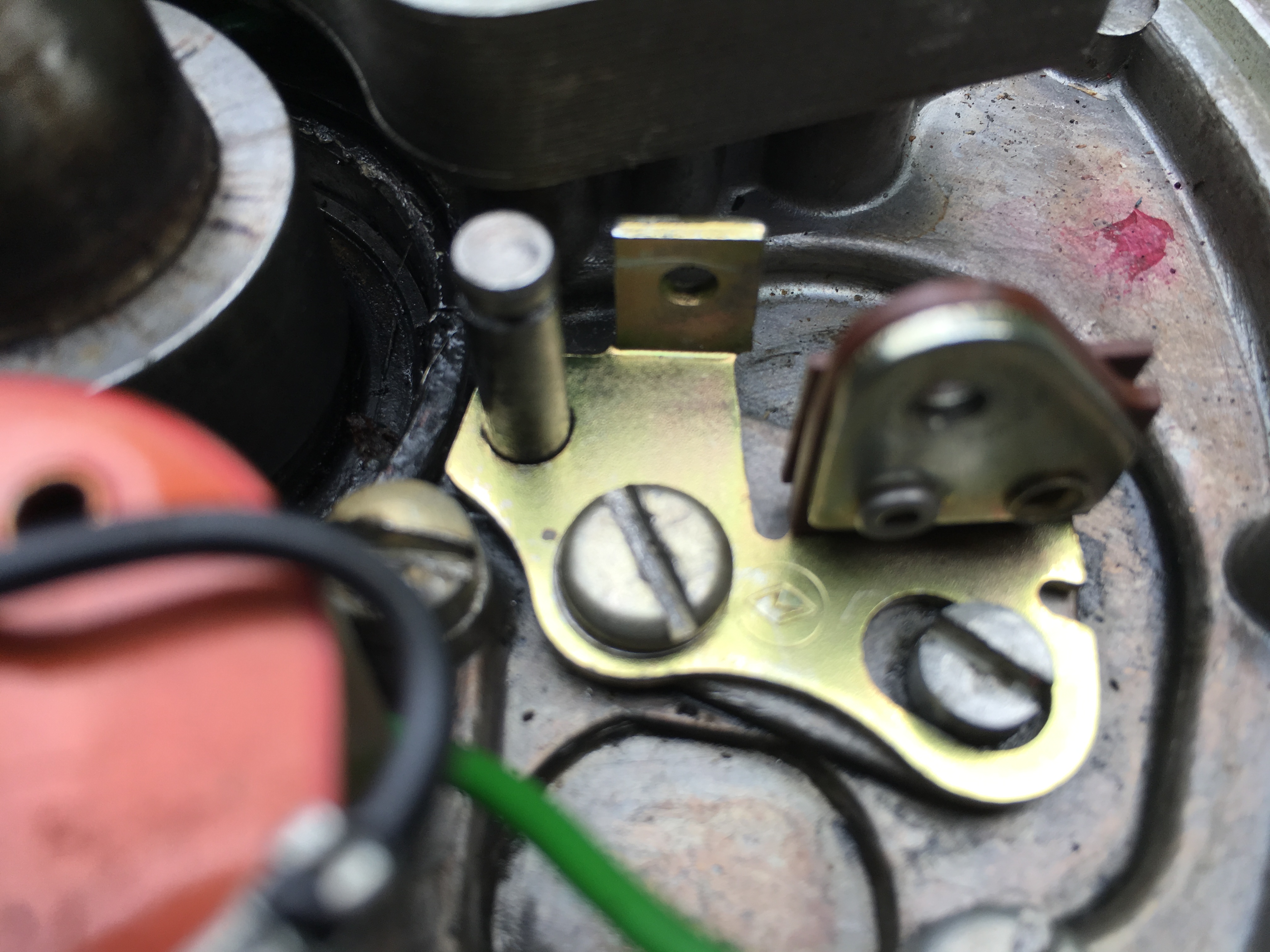
I worked on my 1956 Evinrude 15HP today and made some great strides. I figured out how I am going to mount my transistors for 2 cylinder omc motors 2 stroke of course. Take a look at the pics. Using half a set of evinrude/johnson points is how I am doing it. The half set of OMC points are already insulated against ground and they have metal tapped for screw plate on them for my heat shield. Best part of all is all the original screws can stay in the engine if you desire. If someone wants they can swap it right back to a points system with a new set of points and condensers since all original omc screws are in place. You can see how I mount the transistor to a half set of omc points. I took a pic of only the transistor on the half set of points so you could tell how I am doing it I then took it back off motor and soldered everything to the transistor and then screwed it back on.
One other thing I learned today is that I had to switch the polarity of my wires to get the module to fire on the this omc engine on my other omc engine they were the opposite. Whats great about the way I am mounting them is you just switch the black and red wires from ground to the small positive primary wire that goes to coil. Also check out the cheapo spark tester in pics if it won’t light up when you spin flywheel clockwise like normal try spinning it backwards and if it lights up wires are reversed and need switching. Now that redneck technology at its best.
I am going to post more on my how to’s and where I am getting parts later. I think I can build these for less than 2 dollars a piece. Got parts on order going to build some more on the cheap and test them then report back. Right now waiting on parts.
Joe
ps take a look at the first pic with red and black wires those are the ones you reverse if your not getting fire to spark plug.
Attachments:
https://SecreLocal.com - - No Verify - Anonymous Adult Dating -