Home › Forum › Ask A Member › Mercotronic Model 98 and Model 9800 Information › Reply To: Mercotronic Model 98 and Model 9800 Information

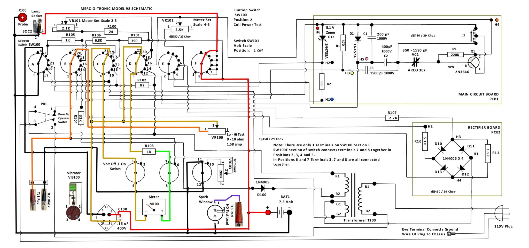
It would not be that hard to create a single circuit to test coils under load but you would have to be careful to keep the input current to a low value so the coil was not damaged similar to how the Mercotronic does it. I have attached a copy of the Model 98 highlighted schematic with the switches set to coil test position as a guide you could use. As you can see it uses a high wattage 10 ohm wire wound variable ohm resistor to control the current going to the coil under test. If you check out the link I posted about the vibrator you can see how a DPDT relay can be configured as an oscillator to replace the vibrator contacts. Another way to open and close the circuit going to the coil under test so it fires repeatedly would be to use an actual point set with a cam operated with a cordless drill. You would need to connect a capacitor that is about 0.15 uF in value and rated for at least 400 volts to protect the contacts on the relay or the point set and to make the coil oscillate properly each time the points open. The capacitor would need to be connected across the contacts as this reduces the arcing as they open and close each time. The variable resistor would need to be rated at whatever voltage and current you will be using to test the coil. A Mercotronic uses a 7.5 volt DC battery to test most coils and the meter is calibrated to supply up to 4 amps of current. Volts times amps equals Watts so you would need a 10 ohm wire wound variable resistor rated at ( 7.5 x 4 = 30) at least 30 watts to handle the current. You can find these shown on Amazon or other sources. https://www.amazon.ca/Variable-Resistor-Rheostat-cer%C3%A1mica-Reostato/dp/B08LDVLMTL/ref=sr_1_1_sspa?crid=2L1HTV1384DFP&keywords=10+ohm+wire+wound+variable+resistor&qid=1678974528&s=hi&sprefix=10+ohm+wire+wound+variable+resistor%2Ctools%2C77&sr=1-1-spons&psc=1&spLa=ZW5jcnlwdGVkUXVhbGlmaWVyPUEyOTdUQlJIVDE5OElOJmVuY3J5cHRlZElkPUEwMTIwNTg3OUtMNkM5Mk9RQU9DJmVuY3J5cHRlZEFkSWQ9QTA4ODE3MDUyREI3SkdKSlNNVU1VJndpZGdldE5hbWU9c3BfYXRmJmFjdGlvbj1jbGlja1JlZGlyZWN0JmRvTm90TG9nQ2xpY2s9dHJ1ZQ== A simple power supply could be five 1.5volt D cell batteries connected in series to obtain the 7.5 volt potential difference – you could make your own holder or purchase a couple that are made to hold four and wire them accordingly jumpering the unfilled portions of the holder. I would suggest using a spring loaded momentary on switch so that you are not tempted to power the coil for any great length of time. A spark plug with a widened gap could be connected to the secondary terminal or plug wire of the coil to serve the same function as the spark window. If the gap is normally about .025″ in the engine spark plug a gap of .075″ should allow the coil to be tested at atmospheric pressure. Since a spark plug inside a cylinder under compression requires a good spark to fire widening the gap should simulate the plug firing under compression. For an amp meter so you know how much current is being delivered to the coil you could try using a digital amp meter (if you have a multimeter with that option that is rated at 10 amps) connected in series in the coil circuit. Some digital ammeters do not like to measure interrupted current circuits with high voltage spikes (which an ignition coil produces – can be as high as 175 volts) very well. I would recommend using a dedicated analog ammeter that is rated 0 – 5 amps – these can be found on amazon or other sources as well. https://www.amazon.ca/uxcell%C2%AE-Rectangle-Current-Analogue-Ammeter/dp/B01LWC6LBD/ref=dp_prsubs_2?pd_rd_w=Ftc54&content-id=amzn1.sym.eb47624e-b593-4e5a-85a6-6fa2045b926c&pf_rd_p=eb47624e-b593-4e5a-85a6-6fa2045b926c&pf_rd_r=W6RPX47NR8WR4MC97MX5&pd_rd_wg=xcBhl&pd_rd_r=d930c3d4-9a64-40d9-9512-af8e64417085&pd_rd_i=B01LWC6LBD&psc=1
As always if you decide to construct such a coil tester do it with safety in mind. The variable resistor can become quite warm or even hot during a test and can burn skin. Ignition coils are designed to develop high voltage (20000 volts or more usually) that can shock or even kill so use the appropriate rated wiring for the primary and secondary circuits. These are just some suggestions to consider – it is up to you to determine if you have the necessary skills to construct a tester that will operate safely for you and anyone else that may be tempted to use it. Hope this provides some helpful information for you.