Home › Forum › Ask A Member › Scott McCulloch 25 › Reply To: Scott McCulloch 25

This is getting almost off topic, but since there is such a “why” or “how” question, I am going to attempt to explain how an outboard alternator charging system works. So hang onto your hats folks, here goes.
First, I must say that this is how I was taught. See, my schooling was when I took a course in radio/TV repair, back when radios and TVs had vacuum tubes. The first lessons were on what electricity is and how it flows. One of the hardest things for me to grasp is that it flows from negative to positive. That is, it comes out of a battery’s negative terminal, flows through a load, and back into the positive terminal to complete a circuit. That is known as the “Electron Theory” and is how it REALLY flows. It would be almost impossible to understand how a vacuum tube works without the Electron Theory. Contrast that with the “Conventional Theory” which teaches that it flows from positive to negative–that is out of the + terminal and back to the – terminal. Since vacuum tubes are rarely seen any more, the Electron theory has more or less fallen into disuse and Conventional Theory used instead, because that is how most people THINK it flows. My comments from here on use the real Electron theory. If you insist on using the Conventional Theory, simply reverse the arrows.
Ok now that I have everyone confused, a battery supplies a voltage that pushes electrons out of the negative terminal, through a load, and back into the positive terminal. Now, for lesson two: To recharge that battery, a voltage that is higher than the battery’s voltage it applied to it, which causes the electrons to flow backwards through the battery, recharging it. That is, the charging current flows into the battery’s negative terminal and out the positive terminal and back to the charger source. EDIT: Corrected.
Finally, on to the charger and rectifier. But first, I must explain that the current flows through a diode in a direction OPPOSITE the direction of the diode symbol’s arrow and is blocked in the opposite direction (Electron theory). There is a reason for that seemingly backwards arrow, which I’m not going to get into. Reverse it if you want to think Conventional.
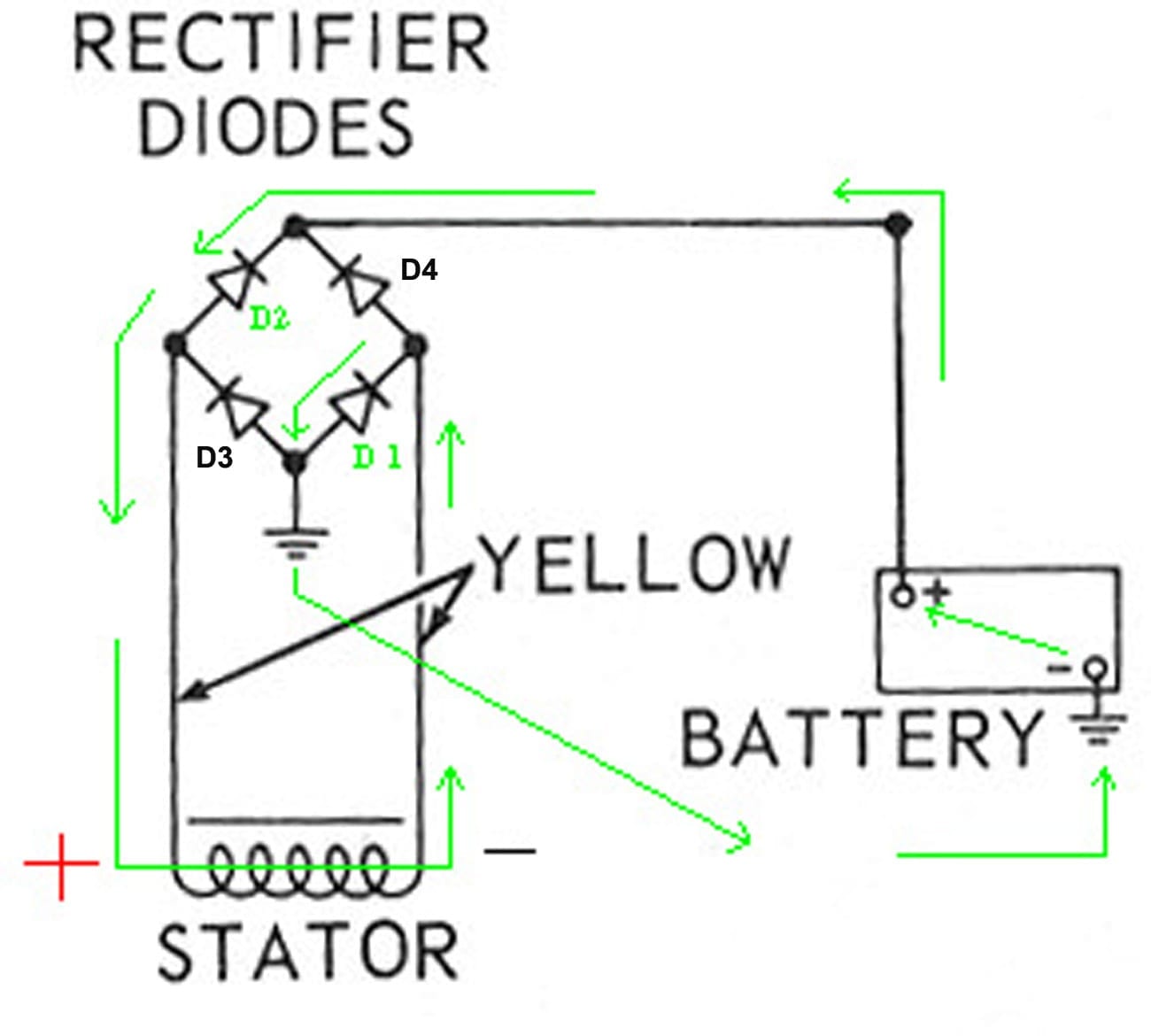
Following is a diagram of a simple outboard alternator, using a bridge rectifier (the most common type). Try to follow along, and bear with me.
The Stator Coil: Follow the green arrows. As a magnet passes the coil, a voltage is generated in the coil, one end will be positive, the other end negative, according to which end of the magnet passes by first. As the other end of the magnet passes by, the polarity of the voltage is reversed. For this study, consider the right end of the coil is negative, the left is positive. If the voltage exceeds the voltage of the battery, electrons will flow out of the negative end of the coil, through Diode D1, to ground, then from ground into the negative terminal of the battery (remember, this is backwards and charging the battery). After passing through the battery and out of the positive terminal they go back to the rectifier Diode D2 and to the coil positive end to complete the circuit. During this time, Diodes D3 and D4 are blocking current flow in the wrong direction. As the magnet continues, the coil ends change polarity and current now passes through D3 an D4, with D1 and D2 blocking, but never mind that for right now.
Disconnect the battery and see what happens: In the previous example, voltage is limited by what ever it takes to overcome the resistance of the battery. With no battery, voltage is only limited by the strength and speed of the magnet, and the windings of the coil. It can easily reach 100 Volts or more, for example. Now we have 100V pushing electrons through D1, but they do not go to ground because the ground circuit is open (no battery). Instead, they look at Diode D3 as a path back to the coil. D3 tries to block them, but lets say D3 cannot withstand more than 50 Volts in backwards flow. So here we have 100V trying to flow backwards through D3 which can only withstand 50V. Result is D3 burns up and the smoke gets out.
If you were able to wade through all this, good.